I saved an old 'IBM Aptiva 2190' computer from a hard rubbish, although after a while of troubleshooting trying to get it to work, I determined that both, the power supply and motherboard had died.
I did have plans to strip all the hardware from the case and turn it into a 'sleeper computer', although I realized that that wasn't going to happen due to financial reasons. I did however still want to do something with the case, as it was a really nice-looking design.
I liked the fact that it was designed horizontally and figured that it would make a pretty cool bedside table but thought that it would look pretty plain.

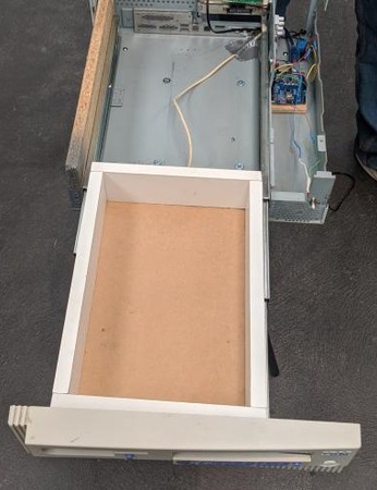
I managed to remove the front face of the case and build in a drawer by adding some drawer runners and building a draw out of some spare white laminate wood that I had lying around. It was at this point that I could stick it on some legs and call it done.
But I decided I wanted more. A bedside table needs a lamp. So, I found a lamp at my local Bunnings, removed the desk clip and drilled a hole in the top of the case to mount it.
I bought an Arduino Uno clone for about $5AUD from AliExpress, along with a $2.50AUD relay, and a couple of LEDs.
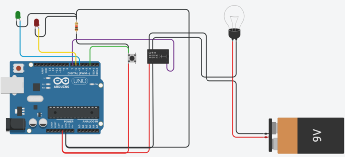
I wired up all my electronics as per the circuit diagram that I made below.
I loaded the following code onto the Arduino that I wrote using the Arduino software.
							int buttonpin = 2;
int relaypin = 7;
bool buttonOn = false;
int blinkerpin = 6;
int powerlight = 5;
int ondelay = 100;
int offdelay = 100;
int addoffdelay = 0;
int addoffdelaytime = 0;
int status = false;

void setup(){
Serial.begin(9600);
pinMode(blinkerpin, OUTPUT);
pinMode(powerlight, OUTPUT);
pinMode(buttonpin, INPUT_PULLUP);
pinMode(relaypin, OUTPUT);
		}

void loop(){
  digitalWrite(blinkerpin, LOW);
  digitalWrite(powerlight, LOW);
  Serial.print(buttonOn, DEC);
  digitalWrite(relaypin, HIGH);
if(digitalRead(buttonpin) == true){
  buttonOn = !buttonOn;
  delay(300);
  while(buttonOn == true){
	lighting();
	digitalWrite(relaypin, LOW);
  }
}
}

void lighting(){
  digitalWrite(powerlight, HIGH);
  Serial.print("Loop");
  addoffdelay = random(0,45);

  if(addoffdelay >= 41){
	  ondelay = random(25, 75);
	  offdelay = random(5, 300);
	  digitalWrite(blinkerpin, HIGH);
	  delay(ondelay);
	  digitalWrite(blinkerpin, LOW);
	  delay(offdelay);
	  addoffdelaytime = random(1000, 4500);
	  delay(addoffdelaytime);
	 }
	 else if (addoffdelay <= 40){
	  ondelay = random(25, 75);
	  offdelay = random(5, 300);
	  digitalWrite(blinkerpin, HIGH);
	  delay(ondelay);
	  digitalWrite(blinkerpin, LOW);
	  delay(offdelay);
	}
 loop();
	}
The code has a function that generates random flashes and delays for the 'hard drive indicator light', toggles the lights on and off and controls the relay.
I attached some legs that I found on another table from a hard rubbish, and I was pleased to notice that they were a perfect match to the lamp that I used.
Below is a video of how the table operates.